
Design Smarter, Not Harder: Introducing SolidWorks 3D Layouts
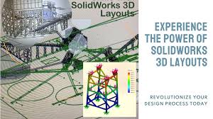
Design Smarter, Not Harder: Introducing SolidWorks 3D Layouts Are you still chained to the limitations of 2D drawings? It’s time to break free and revolutionize your design process with SolidWorks 3D layouts. SolidWorks 3D Layouts allows you to create skeletal structures of your designs using simple 3D sketches. These layouts serve as the foundation for your projects, making it easier to: Visualize spatial relationships Test different configurations quickly Identify potential issues early in the design process Optimize Efficiency: 3D Rock Crusher Plant Design Real-World Impact: Companies using SolidWorks 3D Layouts have reported: Up to 30% reduction in design time 25% fewer revisions needed Improved client satisfaction due to clearer initial presentations Master Space and Structure: SolidWorks 3D Layout Ready to transform your design process? Join our services platform to see SolidWorks 3D Layouts in action and learn how it can elevate your design capabilities. Design smarter, not harder: Book expert SolidWorks design and FEA services now at https://www.fiverr.com/s/2KA28Bq and revolutionize your product development process! Expert SolidWorks Design & FEA Services Available Now Don’t miss this opportunity to stay ahead of the curve and design smarter, not harder! Would you like me to expand on any part of this content or make any adjustments? Benefits of 3D Layouts: Discover how to: Visualize with Impact: Create immersive 3D models that bring your designs to life. Collaborate Seamlessly: Share your vision with clients and stakeholders through interactive 3D models. Streamline Documentation: Generate precise 2D drawings directly from your 3D model using MBD. Optimize Performance: Conduct FEA analysis to enhance product efficiency and durability. Elevate Your Facility: 3D Plant Layout Critique & Optimization Real-World Applications: Whether you’re designing for the pollution control board, factories, boilers, or any other industry, SolidWorks 3D layouts provide a solid foundation for your project. Create accurate and detailed submissions with ease, while ensuring compliance with regulatory requirements. Precision 2D Blueprints: Approval-Ready Documentation Conclusion: By adopting SolidWorks 3D modeling, you will not only improve your design process but also gain a competitive edge in the market. Say goodbye to the limitations of 2D drawings and unlock the full potential of your projects. Don’t let outdated methods hinder your success. Embrace the future of design with SolidWorks 3D Layouts today! #SolidWorks #3DModeling #ProductDesign #Engineering #CAD #FEA #Manufacturing #Plant #Layout #MBD Jinto A J Share this : Facebook Instagram Linkedin
The Power of Hole Features in SolidWorks
Seismic Analysis Simplified: Static vs Dynamic There are several advantages to using the Hole Wizard or creating assembly-level holes in SolidWorks assemblies, rather than including pre-drilled holes in individual parts: 1. Maintainability and Efficiency: Reduced File Size: Parts without pre-drilled holes are generally smaller in file size, leading to faster loading times and improved overall assembly performance. Change Management: If the hole pattern or size needs modification, editing the assembly-level hole feature updates all relevant parts simultaneously, saving time and reducing the risk of inconsistencies. Part Reusability: Parts without holes can be used in different assemblies, promoting design reuse and reducing the need for multiple part variations. Type of Holes 2. Bottom-Up vs. Top-Down Design: Assembly-Driven Design: The assembly dictates the hole requirements, allowing for a more top-down design approach where the overall functionality of the assembly takes precedence. Flexibility: Assembly-level holes provide flexibility. You can decide whether to propagate the holes to all parts, specific parts, or exclude certain components based on their needs. Assembly Features – Holes 3. Addressing Manufacturing Considerations: Machining Sequence: Assembly-level holes can reflect real-world manufacturing scenarios where holes might be drilled after components are assembled for better alignment or access. Part Integrity: Parts without holes might be sturdier during the machining process, especially for thin sheet metal parts, as pre-drilled holes can introduce stress concentrations. Work Flow for Hole Series Tool 4. Collaboration and Communication: Clear Design Intent: Assembly-level holes can clearly communicate the design intent for hole locations and sizes to manufacturing partners who might not have access to individual part files. Reduced Confusion: Eliminating pre-drilled holes in parts avoids potential confusion for downstream users who might misinterpret their purpose or accidentally modify them. Here’s a table summarizing the advantages: Hole Feature : Advantages However, there are also some situations where using pre-drilled holes in parts might be preferable: Simple Assemblies: For very simple assemblies with few parts and a fixed hole pattern, pre-drilled holes might be more straightforward. Top-Down Design with Known Requirements: If the hole requirements are fully defined at the part level, including them upfront might be suitable. External Reference for Holes: If holes are created based on external references or dimensions not directly related to the assembly, defining them in parts can be appropriate. Ultimately, the best approach depends on your specific design, manufacturing considerations, and collaboration needs. Weigh the advantages of assembly-level holes against the potential benefits of pre-drilled holes in parts to make an informed decision for your project. Shall we count holes in assembly rather than putting bolts and nuts to reduce system performance issues? Here’s a breakdown of the pros and cons of counting holes in an assembly versus using bolts and nuts to address system performance concerns in SolidWorks: Structural Design for Pipe Line Installation using Solidworks Counting Holes (Assembly Level): Pros: Performance Improvement: Reduces assembly file size and complexity, potentially leading to faster loading times and smoother manipulation within SolidWorks. Maintainability: Easier to modify hole patterns across all parts if the design changes. Design Intent: Clearly communicates hole placement for manufacturing purposes. Cons: Limited Functionality: You cannot define specific bolt types, torques, or preload information, which might be important for engineering calculations. Visualization Issues: The assembly might not visually represent the actual bolted connection, potentially impacting clarity for non-technical users. Missing Information for Manufacturing: Downstream users like machinists might require additional information about bolt types and specifications if not explicitly shown in the model. Using Bolts and Nuts: Pros: Accurate Representation: Provides a more realistic visualization of the bolted connection, enhancing clarity for users. Engineering Data: Allows you to define bolt types, torques, and preload, which can be valuable for engineering calculations. Manufacturing Clarity: Clearly communicates bolt specifications to manufacturing partners. Cons: Performance Impact: Large assemblies with many bolts and nuts can increase file size and potentially slow down SolidWorks performance. Editing Complexity: Modifying hole patterns or bolt specifications might require edits in multiple parts, increasing editing time. Fasteners Feature in Solidworks Here are some additional factors to consider: Assembly Complexity: For very complex assemblies with numerous fasteners, counting holes might be more efficient for performance reasons. Design Intent Communication: If clear communication of bolt types and torques is crucial, using bolts and nuts is essential. Downstream Users: Consider the needs of downstream users like machinists who might require clear information about bolts and nuts. Finding a Balance: In some cases, you might find a middle ground. You could use a combination of approaches: Use assembly-level holes for some generic hole patterns where bolt specifics are not critical. Use bolts and nuts for key connections where accurate representation, engineering data, and clear communication of bolt specifications are essential. Ultimately, the decision depends on your specific needs and priorities. If performance is a major concern and bolt details are not critical, counting holes might be a suitable option. If accurate representation, engineering data, and clear communication of bolted connections are essential, using bolts and nuts is the way to go. Here are some additional tips for optimizing assembly performance in SolidWorks: Large Assembly Tools: Explore SolidWorks tools specifically designed for handling large assemblies, like lightweight components and simplification techniques. Component Suppression: Suppress unnecessary components during editing to improve performance. Display Settings: Adjust display settings to reduce graphical detail when performance is a priority. Hardware Acceleration: If your graphics card supports it, enable hardware acceleration in SolidWorks for potential performance gains. Fasteners using Solidworks By carefully considering these factors and exploring optimization techniques, you can achieve a balance between performance and efficient design communication in your SolidWorks assemblies. Jinto A J Share this : Facebook Instagram Linkedin
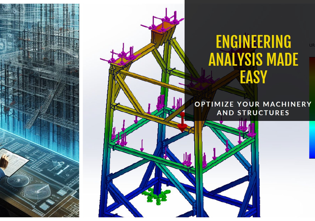
Seismic Analysis Simplified: Static vs Dynamic

Seismic Analysis Simplified: Static vs Dynamic Achieve Faster Seismic Analysis Results with Static Equivalent Lateral Force (ELF) Procedures! In the world of structural engineering, seismic analysis is crucial for ensuring building safety. While dynamic analysis methods like response spectrum are powerful, they can be time-consuming and require high-powered workstations. This newsletter explores a practical alternative: Static Equivalent Lateral Force (ELF) Procedures …. Static Load Combinations for Seismic Analysis : Solidworks Simulation Traditional Dynamic Analysis: Advantages: Highly accurate for complex structures. Disadvantages: Time-consuming, requires advanced software and powerful computers. Static ELF Approach: Static Analysis – Simulation Tree : Solidworks Simulation Advantages: Faster analysis – Can be completed within less than 30 minutes! Less demanding on computational resources. Easier to understand and implement. Assigning Seismic Loads -01: Solidworks Simulation Assigning Seismic Loads -02: Solidworks Simulation Disadvantages: Less precise than dynamic methods for complex structures. When is Static ELF a Good Choice? For many common building types. When adhering to international building codes like ASCE 7-22, IBC 2021/2024, or SBC 301 (especially in KSA or in GCC countries). The Power of Spreadsheets: My previous newsletter introduced a smart seismic design calculator that streamlines base shear calculations following your chosen standard. Seismic Loads Calculator – Spreadsheet https://www.linkedin.com/pulse/smart-seismic-design-ai-powered-calculator-tailors-loads-jinto-a-j-tu8xc Benefits: Reduced Analysis Time: Go from days to minutes! Simplified Workflow: Apply calculated base shears as static loads in your FEA software. Improved Efficiency: Focus your resources on complex projects requiring dynamic analysis. Embrace Efficiency! Static ELF procedures offer a valuable tool for faster and more accessible seismic analysis, particularly for standard building designs. Leverage them alongside spreadsheet calculators for a streamlined workflow. Stress Plot – Solidworks Simulation Stress on Probes – Solidworks Simulation Jinto A J Share this : Facebook Instagram Linkedin
Designing Steel Structures Against Earthquakes and Wind !!!

Designing Steel Structures Against Earthquakes and Wind !!! In regions prone to earthquakes and strong winds, the selection of appropriate structural elements is critical for building safety and longevity. Moment-resisting frames (MRFs) play a vital role in these environments, efficiently transferring both seismic and wind-induced forces from the structure to its foundation. These versatile systems offer varying degrees of resistance and flexibility, adapting to different risk levels Steel structures in earthquake zones requires careful consideration of structural elements. Moment-resisting frames (MRFs) play a crucial role, transferring seismic forces from the ground to the foundation. This table compares three types of MRFs: Ordinary Moment Resisting Frames (OMRFs): These are the simplest and most economical option, ideal for low seismic zones. Their beam-to-column connections (shown in gray) offer limited flexibility. Best suited for:Low seismic zones Characteristics: Simplest and most economical option Beam-to-column connections: Limited flexibility (typically shown in gray) Intermediate Moment Resisting Frames (IMRFs): A step up in complexity, IMRFs are suitable for moderate seismic zones. Their connections (shown in orange) allow for some deformation, indicated by the increased red area in most of the finite element analysis deformation or Von-mises stress plots. Best suited for: Moderate seismic zones Characteristics:Increased complexity compared to OMRFs Connections:Allow for some deformation Special Moment Resisting Frames (SMRFs): The most robust option, SMRFs are designed for high seismic zones. Their specially engineered connections (shown in deep red) provide the highest level of ductility, enabling them to bend and absorb significant energy during an earthquake. Best suited for: High seismic zones Characteristics: Most robust option Connections: Specially engineered for maximum ductility (typically shown in deep red) Performance: Can bend and absorb significant energy during earthquakes Ordinary Moment Resisting Frames (OMRFs): These are the simplest and most economical option, ideal for low seismic zones. Their beam-to-column connections (shown in gray) offer limited flexibility. Intermediate Moment Resisting Frames (IMRFs): A step up in complexity, IMRFs are suitable for moderate seismic zones. Their connections (shown in orange) allow for some deformation, indicated by the increased red area. Special Moment Resisting Frames (SMRFs): The most robust option, SMRFs are designed for high seismic zones. Their specially engineered connections (shown in deep red) provide the highest level of ductility, enabling them to bend and absorb significant energy during an earthquake. Demystifying Frame Stability – Perfect, Redundant, and Deficient Designs This work explores the concept of frame stability in structural engineering. It defines three key categories: perfect frames, redundant frames, and deficient frames. Perfect frames: These structures achieve stability with the minimum necessary members, ensuring efficient load transfer through static equilibrium analysis. Redundant frames: Over-constrained with additional members, these frames require advanced methods beyond basic statics to determine internal forces due to their inherent redundancy. Deficient frames: Lacking the minimum required members, these structures are inherently unstable and unsuitable for real-world applications. The distinction between these categories hinges on the relationship between the number of members, degrees of freedom, and support reactions. Understanding these concepts is crucial for structural engineers to design safe, efficient, and reliable structures. Here are some basic equations to understand perfect, redundant, and deficient frames: 1. Degrees of Freedom (DOF): The number of degrees of freedom (DOF) represents the independent ways a structure can move or rotate if its supports are completely removed. Equation: DOF = 3n (for a 3D structure) + m (for a 2D structure) where: n = number of nodes (joints where members connect) m = number of movable supports (hinges or rollers) 2. Supports and Reactions: Supports provide external constraints that prevent the structure from collapsing. Each support can provide a specific number of reactions (forces or moments) that resist the applied loads. Common Support Reactions: Hinge: Provides two reactions – one vertical and one horizontal force. Roller: Provides one reaction – a force in the direction of the roller. Fixed support: Provides three reactions – one vertical and one horizontal force, and one moment. 3. Identifying Perfect, Redundant, and Deficient Frames: Perfect Frame: A perfect frame has a number of independent reactions (R) equal to the number of degrees of freedom (DOF). Equation: R = DOF Redundant Frame: A redundant frame has a number of independent reactions (R) less than the number of degrees of freedom (DOF). Equation: R < DOF Deficient Frame: A deficient frame has a number of independent reactions (R) greater than the number of degrees of freedom (DOF). Equation: R > DOF Note: These equations provide a basic understanding. Analyzing real-world structures often requires more complex methods like the method of joints or the method of sections. Additional Considerations: Formula: m: Number of members in the frame j: Number of joints in the frame This formula relates the number of members (m) to the number of joints (j) to determine the frame’s stability category. Interpreting the Formula: Perfect Frame (m = 2j – 3): If the number of members (m) equals 2 times the number of joints (j) minus 3, the frame is considered a perfect frame. This means it has the minimum number of members required for stability and can be analyzed using only the equations of static equilibrium. Redundant Frame (m > 2j – 3): If the number of members (m) is greater than 2 times the number of joints (j) minus 3, the frame is considered redundant. It has more members than necessary for stability, introducing additional constraints that require advanced analysis methods beyond basic statics. Deficient Frame (m < 2j – 3): If the number of members (m) is less than 2 times the number of joints (j) minus 3, the frame is considered deficient. It lacks the minimum members required for stability and is unsuitable for real-world applications due to potential instability under load. Benefits of the Formula: This formula provides a quick and easy way to categorize simple planar trusses (structures in a single plane) based on their member count and joint connections. It helps engineers identify potential stability issues in the initial stages of design. Limitations of the Formula: Applicability: The formula
Revolutionizing Design
Revolutionizing Design: How AI is Supercharging Mechanical Engineering with FEA The world of mechanical engineering is undergoing a transformative shift with the integration of Artificial Intelligence (AI) and Finite Element Analysis (FEA). This powerful combination is streamlining workflows, optimizing designs, and pushing the boundaries of innovation. The Power of FEA: FEA has long been a cornerstone of mechanical engineering, allowing engineers to simulate real-world conditions and analyze product performance virtually. However, traditional FEA processes can be time-consuming and require significant expertise. AI Steps Up the Game: AI is injecting new life into FEA by: Automating Mesh Generation: AI algorithms can automatically create optimal meshes for complex geometries, saving engineers valuable time. Material Property Prediction: AI can predict material behavior based on existing data, reducing the need for extensive physical testing. Design Optimization: AI can explore vast design variations and identify the most efficient and effective solutions, leading to lighter, stronger, and more sustainable products. Predictive Maintenance: AI can analyze FEA results and predict potential failures before they occur, enabling proactive maintenance strategies. Benefits for Engineers: Increased Efficiency: AI automates tedious tasks, allowing engineers to focus on higher-level design challenges. Enhanced Design Exploration: AI empowers engineers to explore a broader range of design possibilities, leading to more innovative solutions. Improved Decision-Making: AI provides valuable insights into product performance, allowing engineers to make more informed decisions. Reduced Costs: AI can help optimize designs for efficiency, leading to cost savings in material usage and manufacturing processes. The Future is Now: The integration of AI and FEA is still evolving, but its potential is undeniable. As AI algorithms continue to develop, we can expect even greater advancements in design optimization, material selection, and overall product performance. Jinto A J Share this : Facebook Instagram Linkedin Related